Pump Vibration Monitoring
- How pump vibration monitoring works
- The pump problems it can detect
- Where it’s used in real applications
- How Metrix vibration equipment and Clipper Controls work together to implement a practical, right-sized monitoring strategy

👉 Contact Clipper Controls today to specify the right pump monitoring solutions for your facility.
Send us a message or call us at (844) 880-2469
Why Pump Vibration Monitoring Matters for Critical Pumps
- Shut down a clarifier, lift station, or process line
- Force emergency bypass or discharge, increasing environmental and safety risks
- Drive up overtime and rush-repair costs
- Shorten the life of motors, couplings, seals, and bearings
- Run to failure → reacting after the fact
- Calendar-based PM → doing work whether it’s needed or not
- Condition-based / predictive maintenance → using real vibration data to decide when to intervene
- Not every pump needs continuous monitoring—but pumps with high consequence of failure, difficult access, or critical impact on flow or quality usually do.
How Pump Vibration Monitoring Works
What Vibration Sensors Measure on Pumps
- Velocity sensors or accelerometers mounted on the pump or motor casing
- Measuring vibration in units such as mm/s or inches per second (ips) for velocity, or g’s for acceleration
- Tracking both:
- Overall vibration level (how “rough” the machine is running)
- Frequency content (which speeds or harmonics are causing the vibration)
Where Sensors Are Installed on Pump Systems
- Motor inboard and outboard bearings
- Pump inboard and outboard bearings
- Casing or bearing housings near points of highest vibration response
- The motor and upper bearing housings
- The support structure or pedestal, where vibration from the submerged stages is transmitted
- Piping vibration near the pump discharge or suction, where hydraulic issues or resonance can show up
- Nearby structures or baseplates when looseness or soft foot is suspected
| Measurement Location | Common Purpose | Problems It Can Help Identify |
|---|---|---|
| Pump inboard bearing | Monitor vibration near the coupling and pump shaft | Misalignment, bearing wear, looseness, coupling-related vibration |
| Pump outboard bearing | Monitor vibration near the pump end of the rotating assembly | Imbalance, bearing wear, impeller-related vibration |
| Motor inboard bearing | Evaluate coupling-side motor vibration | Misalignment, bearing problems, looseness |
| Motor outboard bearing | Evaluate motor-side vibration independently from the pump | Motor imbalance, bearing wear, motor-related faults |
| Axial direction near a thrust-bearing location | Monitor vibration along the shaft axis | Misalignment, thrust-related issues, coupling problems |
| Pump casing or bearing housing | Measure overall machine vibration and establish trends | General vibration severity, imbalance, looseness, bearing degradation |
| Baseplate, pedestal, or support structure | Evaluate structural vibration transmitted through the installation | Looseness, soft foot, foundation problems, resonance |
| Suction or discharge piping | Investigate vibration associated with hydraulic or piping conditions | Cavitation, pulsation, piping resonance, hydraulic instability |
Interpreting Vibration Signatures (At a High Level)
- Running speed (1×) is the pump’s operating speed; many faults show up here or at multiples of this frequency.
- Imbalance typically shows up as elevated vibration at 1× running speed.
- Misalignment and looseness often create vibration at 1×, 2×, and higher harmonics.
- Bearing defects tend to excite higher-frequency bands and grow gradually over time.
- A single overall vibration value (e.g., in ips)
- Warnings and trips when vibration exceeds configured thresholds
What Is an Acceptable Vibration Level for a Pump?
- Applicable pump vibration standards
- Pump and motor manufacturer recommendations
- Baseline vibration measured under normal operating conditions
- Changes in vibration over time
- The operating condition of the pump when the measurement is taken
| Vibration Pattern | Possible Cause | What Else to Check |
|---|---|---|
| Strong vibration at 1× running speed | Rotor or impeller imbalance | Impeller buildup, erosion, balance condition, bent shaft, recent repair work |
| Elevated vibration at 1× and 2× running speed | Shaft or coupling misalignment | Coupling condition, shaft alignment, soft foot, bearing temperature |
| Multiple harmonics of running speed | Mechanical looseness or structural movement | Anchor bolts, bearing fits, baseplate, grout, foundation condition |
| Increasing high-frequency vibration | Bearing deterioration or lubrication problem | Bearing temperature, lubrication condition, contamination, abnormal noise |
| Broadband high-frequency vibration with unstable flow or pressure | Cavitation or hydraulic instability | NPSH conditions, suction restrictions, valve position, wet-well level, operating point |
| Sudden vibration increase after maintenance | Installation, alignment, or assembly problem | Shaft alignment, soft foot, piping strain, fastener torque, sensor mounting |
| Vibration changes significantly as pump speed changes | Possible resonance or variable-speed operating issue | Support structure, natural frequency, VFD operating range, piping response |
Important: Vibration frequency or amplitude should not be used by itself to diagnose a pump fault. Similar vibration patterns can have multiple causes, so vibration data should be evaluated alongside operating speed, load, flow, pressure, temperature, maintenance history, and other condition data.
Pump Vibration Standards
Why There Is No Universal Pump Vibration Limit
- Pump type and configuration
- Horizontal versus vertical mounting
- Operating speed
- Bearing type
- Pump and motor power
- Foundation and baseplate stiffness
- Measurement direction and sensor location
- Variable-speed operation
- Hydraulic operating point
- Proximity to the pump's best efficiency point (BEP)
- Piping forces and structural resonance
Baseline Vibration vs. Absolute Vibration Limits
- Pump speed
- Flow rate
- Suction pressure
- Discharge pressure
- Motor load
- Valve position or system operating condition
Warning and Trip Levels
- Warning or alarm level: Indicates that vibration has increased enough to justify inspection, trending, or maintenance planning.
- Trip or shutdown level: Indicates vibration has reached a level where continued operation could create an unacceptable risk of equipment damage or failure.
Consider Operating Conditions Before Diagnosing High Vibration
- Pump speed changed
- Flow moved significantly away from the normal operating point
- Suction pressure dropped
- A valve position changed
- The pump began cavitating
- Process density or viscosity changed
- Maintenance was recently performed
- Piping or foundation work occurred
How Should Pump Vibration Limits Be Set?
- Identify the applicable pump, manufacturer, and industry vibration criteria.
- Measure vibration while the pump is operating normally.
- Establish a repeatable baseline at known operating conditions.
- Trend vibration over time rather than relying on isolated measurements.
- Set warning and trip thresholds appropriate for the pump's criticality and operating characteristics.
- Investigate meaningful changes in vibration even when an absolute limit has not yet been exceeded.
Common Pump Problems Detected by Vibration Monitoring
Pump vibration monitoring is most valuable when it points you to specific, fixable problems.
Imbalance
What it is: Uneven distribution of mass around the rotating assembly.
Common Causes:
How it Appears:
Elevated vibration at 1× running speed, often growing over time.
Typical Actions:
- Clean or flush the pump to remove deposits
- Balance or replace the impeller
- Inspect for erosion or damage that may indicate process issues
Misalignment
What it is: The motor and pump shafts are not properly aligned at the coupling.
Common Causes:
- Skid movement or settling
- Inconsistent alignment practices after motor replacement
- Thermal growth not accounted for during alignment
How it Appears:
Elevated vibration at 1× and often 2× running speed, sometimes accompanied by heat at bearings or couplings.
Typical Actions:
- Perform laser alignment and correct angular/offset misalignment
- Check baseplates, shims, and foundation for soft foot or distortion
- Review alignment procedures and standards
Bearing Wear and Lubrication Problems
What it is: Degradation of pump or motor bearings due to wear, contamination, or poor lubrication.
Common Causes:
- Over- or under-lubrication
- Contaminated grease or oil
- Misalignment, imbalance, or excessive loads
How it Appears:
- Increasing overall vibration
- Elevated levels in higher-frequency bands associated with bearing defect frequencies
- Often a gradual upward trend rather than a sudden spike
Typical Actions:
- Plan bearing change-out before catastrophic failure
- Correct underlying causes (alignment, lubrication intervals, contamination, overhung loads)
- Review lubrication type, quantity, and schedule
Looseness and Structural Problems
What it is: Mechanical looseness in the pump, motor, baseplate, or foundation.
Common Causes:
- Loose anchor bolts or hold-downs
- Inadequate grouting or cracked foundations
- Soft foot conditions at motor feet
How it Appears:
- Broadband vibration across multiple frequencies
- Changes in vibration following maintenance, moves, or piping changes
Typical Actions:
- Tighten and torque fasteners to spec
- Re-grout or repair foundations and baseplates
- Diagnose and correct soft foot conditions
Cavitation and Hydraulic Issues
What it is: Formation and collapse of vapor bubbles in the pumped liquid, causing noise, vibration, and damage.
Common Causes:
- Insufficient Net Positive Suction Head (NPSH)
- Low suction levels, clogged strainers, or restrictions
- Over-throttled valves or improper control schemes
How it Appears:
- Distinct “chattering” or “gravel” sound
- High-frequency vibration content that may increase as cavitation worsens
- Often accompanied by flow or pressure fluctuations
Typical Actions:
- Adjust operating conditions (suction head, valve positions)
- Clean strainers and suction piping
- Review pump selection, NPSH margin, and control strategy
👉 Contact Clipper Controls today to specify the right pump monitoring solutions for your facility.
Send us a message or call us at (844) 880-2469
Choosing Between Periodic and Continuous Monitoring
Not every pump needs the same level of monitoring. The right approach depends on criticality, cost, and risk.
| Selection Factor | Periodic Monitoring | Continuous Monitoring |
|---|---|---|
| Pump criticality | Best suited to lower-consequence or redundant pumps | Best suited to critical or high-consequence pumps |
| Data collection | Technician takes readings on a scheduled route | Fixed sensors continuously provide vibration data |
| Fast-developing faults | May occur between inspection intervals | More likely to be detected as conditions change |
| PLC, DCS, or SCADA integration | Usually limited or manual | Common with 4–20 mA or other fixed monitoring signals |
| Automatic alarms | Usually requires technician review | Can provide automatic warning, alarm, or trip functions |
| Remote or difficult access | Less practical when equipment is difficult to reach | Well suited to wet wells, remote stations, galleries, and other difficult locations |
| Initial investment | Generally lower if route-based instruments and personnel are already available | Requires permanently installed sensors, wiring, and monitoring hardware |
| Best fit | Non-critical or easily replaceable pumps | Critical, continuously operating, remote, or difficult-to-access pumps |
Periodic (Route-Based) Vibration Checks
What it is: A technician uses a handheld vibration instrument on a scheduled route (e.g., monthly or quarterly).
Best for:
- Non-critical pumps with low consequence of failure
- Facilities that already have vibration tools and skilled staff
- Verifying the health of pumps that operate intermittently
Limitations:
- Misses short-lived or rapidly developing fault conditions
- Depends heavily on the consistency and skill of the technician
- Provides limited real-time protection between routes
Continuous Online Vibration Monitoring
What it is: Fixed vibration sensors installed permanently on pumps, feeding data to transmitters, local monitors, or control systems.
Best for:
- Critical pumps that must not fail unexpectedly
- Pumps in hard-to-access locations (wet wells, galleries, confined spaces)
- 24/7 operations where a brief shutdown has high cost
Benefits:
- Real-time alarms for sudden changes or unsafe vibration levels
- Trend data that shows the progression of faults
- Integration with SCADA, PLCs, or DCS for unified plant views
How to Decide What Each Pump Needs
- Tier 1 – Critical pumps:
High consequence of failure, safety/environment impact, or costly downtime → Continuous online monitoring. - Tier 2 – Important but not critical pumps:
Noticeable impact when down but with workarounds → Periodic vibration routes plus visual/operational checks. - Tier 3 – Non-critical pumps:
Low-cost, easily replaced, low-consequence → Basic PM, no dedicated vibration monitoring (or spot checks as needed).
Metrix Vibration Monitoring Solutions for Pumps

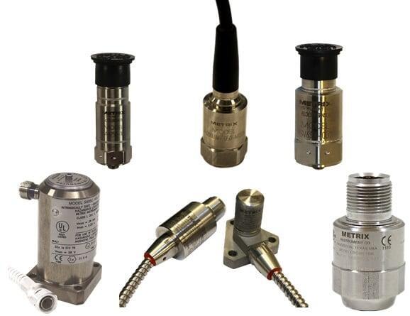
Metrix Vibration Sensors for Pump Applications
- 4–20 mA vibration sensors for simple integration into PLC, DCS, or SCADA systems
- Sensors designed for:
- Constant-duty operation in pump galleries and outdoor stations
- Wet, dusty, or dirty environments around wastewater and slurry systems
- Reliable operation on both motors and pump bearing housings
| Monitoring Goal | Typical Signal or Approach | Best Fit |
|---|---|---|
| Simple overall vibration trending | 4–20 mA vibration transmitter | PLC, DCS, or SCADA trending and alarming |
| High-vibration alarm or shutdown protection | Vibration sensor or transmitter combined with relay monitoring | Critical pump protection and automatic shutdown functions |
| Detailed frequency or spectrum analysis | Dynamic-output accelerometer or compatible vibration sensor | Advanced diagnostics and vibration analysis |
| Local vibration indication | Sensor connected to a local vibration monitor or display | Pump stations, skids, and local control panels |
| Remote continuous condition monitoring | Fixed sensor integrated with the plant control or monitoring system | Unattended stations, critical pumps, and difficult-to-access equipment |
| Basic condition checks on non-critical pumps | Portable or route-based vibration measurement | Facilities using scheduled maintenance inspection routes |
Transmitters, Signal Conditioners, and Local Alarms
- Convert raw sensor signals into standard 4–20 mA outputs representing overall vibration
- Provide relay outputs for alarm and trip levels on high vibration
- Can be mounted in control panels or junction boxes near the pumps
- Adding vibration alarms into pump control panels
- Sending vibration values to remote vibration monitors, I/O racks or SCADA screens
Pump Monitoring Systems and Panels
- Pre-engineered or custom monitoring panels
- Systems that monitor vibration on several pumps and motors
- Panels that include:
- Power supplies, fusing, terminals
- Alarm lights or horn outputs
- Interfaces to plant control systems
Built for Harsh Pump Environments
- Water and wastewater pump stations with high humidity, washdown, and splash zones
- Mining and mineral processing areas with dust, slurry splash, and heavy-duty cycles
- Outdoor booster and transfer stations exposed to temperature extremes
👉 Explore Metrix pump vibration monitoring systems through Clipper Controls, your trusted supplier for reliable industrial instrumentation.
Practical Pump Applications by Industry
Water & Wastewater Treatment
Common pump applications:
- Influent and effluent pumps
- Return activated sludge (RAS) and waste activated sludge (WAS) pumps
- Lift station / wet well pumps
- Chemical metering pumps for coagulants, polymers, and disinfection
What is monitored:
- Vibration on pump and motor bearings for critical process pumps
- Key lift station pumps where failure leads to overflow or bypass
Problems typically caught:
- Misalignment after motor replacement or coupling work
- Cavitation in lift stations at low wet-well levels or high drawdown rates
- Bearing wear in 24/7 sludge and recirculation services
Mining & Mineral Processing
Common pump applications:
- Slurry pumps on grinding and classification circuits
- Tailings and thickener underflow pumps
- Pit and underground dewatering pumps
What is monitored:
- Pump bearing vibration on skid-mounted slurry systems
- Motor vibration on large dewatering and transfer pumps
Problems typically caught:
- Rapid bearing wear from abrasive slurry
- Imbalance from uneven impeller wear and plugging
- Structural looseness on skids that see vibration and movement
Manufacturing & Process Industries
Common pump applications:
- Cooling water and chilled water pumps for process equipment
- Process transfer and recirculation pumps in chemical or food plants
- CIP and washdown system pumps
What is monitored:
- Pumps whose failure can stop a production line or critical batch step
- Pumps that are difficult to access or require long change-out times
Problems typically caught:
- Misalignment after frequent motor swaps
- Looseness and baseplate issues on older equipment
- Bearing problems on pumps that cycle frequently or run at variable speeds
👉 Learn more about vibration condition monitoring solutions from Clipper Controls.
Building a Predictive Maintenance Program for Pumps
- List pumps and assign a criticality score based on:
- Safety and environmental impact
- Production impact and downtime cost
- Repair/replacement cost and lead time
- Designate Tier 1, Tier 2, and Tier 3 pumps.
For pumps selected for monitoring:
- Record vibration at normal operating conditions (flow, pressure, speed).
- Capture baseline data shortly after installation or overhaul.
- Decide which pumps receive:
- Fixed 4–20 mA vibration sensors
- Route-based periodic checks
- Determine how data will be used:
- Direct to PLC/DCS/SCADA for alarming and trending
- Into dedicated Metrix monitors or panels
- Integrated with existing condition-monitoring systems
Ensure compatibility with your control system standards and I/O capacity.
- Set vibration warning and trip thresholds for each monitored pump or use standard guidelines as a starting point.
- Document what happens at each level:
- Warning → schedule inspection or bearing check
- Trip → automatic shutdown and root-cause investigation
This prevents “alarm fatigue” and ensures clear, consistent responses.
- Combine vibration with:
- Bearing or winding temperature
- Suction and discharge pressure
- Flow and motor power
Examples:
- Rising vibration + dropping suction pressure → possible cavitation or suction restriction
- Rising vibration + rising temperature → bearing/lubrication issue
- Stable vibration + falling flow → process or hydraulic issue downstream
- Review vibration trends on critical pumps monthly or quarterly.
- Use the data to:
- Adjust PM schedules
- Improve alignment and installation practices
- Inform future pump and baseplate specifications
- Plan spares for bearings, seals, and critical components
Over time, you’ll build a clearer picture of which pumps are chronic offenders and where design or process changes may be justified.
Working with Clipper Controls on Pump Vibration Projects

Application Review and Asset Survey
- Reviewing P&IDs, pump lists, and process descriptions
- Identifying high-consequence and hard-to-access pumps
- Evaluating environmental conditions (wet wells, galleries, outdoors, hazardous areas)
From there, we help prioritize where vibration monitoring will deliver the most value first.
Application Review and Asset Survey
- Select suitable Metrix vibration sensors and transmitters for each pump
- Recommend sensor mounting locations and wiring practices
- Design panels for single or multi-pump stations that fit your standards
Installation Support, Commissioning, and Training
- Sensor installation best practices and loop checks
- Verifying vibration signal integrity and alarms
- Training on how to interpret alarms and basic trends for pump health
Lifecycle Support and Future Expansion
- Supply replacement sensors and transmitters
- Help add vibration monitoring to new pumps, blowers, and fans
- Assist in integrating more assets into your predictive maintenance strategy
Next Steps: Start Improving Pump Reliability
- Call Clipper Controls:(844) 880-2469
- Or send us a message: visit the Clipper Controls contact page
We can start with your most critical pumps and build a program that fits your budget, your processes, and your maintenance goals.
Page Navigation Links
- Why Pump Vibration Monitoring Matters for Critical Pumps
- How Pump Vibration Monitoring Works
- What Is an Acceptable Vibration Level for a Pump?
- Common Pump Problems Detected by Vibration Monitoring
- Choosing Between Periodic and Continuous Monitoring
- Metrix Vibration Monitoring Solutions for Pumps
- Practical Pump Applications by Industry
- Building a Predictive Maintenance Program for Pumps
- Working with Clipper Controls on Pump Vibration Projects

 Toll Free
