Vibration Sensors for CNC Lathe Spindles and Motors
Modern CNC lathes are asked to do more with less—tighter tolerances, harder materials, longer unattended runs. When spindle or motor vibration starts creeping up, the result is usually the same: chatter, poor surface finish, scrap, and unexpected downtime.
A properly selected vibration sensor for CNC lathes gives you early warning on spindle bearings, motors, and gearboxes so you can schedule repairs before a failure shuts down production.
This page focuses on industrial-grade vibration sensors that integrate with plant PLCs, CNC controls, and condition monitoring systems—not hobby-grade USB or Bluetooth gadgets.
Learn more about rugged vibration sensors and monitoring technologies at Clipper Controls.
Why CNC Lathes Need Vibration Sensors
CNC lathes combine high-speed spindles, precision bearings, and heavy cutting loads. Small vibration problems quickly turn into big ones.
Early warning for spindle bearing failures
Spindle bearings rarely fail “all at once.” They usually pass through a long period of rising vibration and noise. A CNC lathe spindle vibration sensor mounted on the headstock or spindle housing lets you:
- Trend vibration over time instead of relying on “feel”
- Catch bearing defects before they damage the spindle
- Plan repairs during scheduled downtime instead of in the middle of a rush order
Reducing chatter and poor surface finish
Excessive vibration shows up on parts as:
- Chatter marks
- Taper issues
- Dimensional variation
Continuous vibration monitoring helps distinguish between a process problem (tooling, speeds/feeds) and a machine health problem (bearings, alignment, looseness).
Protecting motors, gearboxes, and drives
The main spindle motor, gearboxes, and belt drives are all rotating assets. A CNC machine vibration sensor on these components helps you:
- Detect imbalance, misalignment, or looseness
- Protect against hard failures that can damage windings or gears
- See issues that don’t show up in current draw alone
- Feeding data into plant-wide predictive maintenance
Most plants already monitor pumps, fans, and compressors. Adding vibration monitoring for CNC lathes extends the same predictive maintenance approach to your machine tools, using the same software, dashboards, and alarm strategies.
Industrial-Grade Vibration Sensors vs Hobby CNC Gadgets
Search for “vibration sensor for CNC spindle” and you’ll see everything from consumer accelerometer dongles to full software suites. They’re not all targeting the same use case.
This page is about industrial-grade sensors and transmitters, designed to live on a CNC lathe for years:
- Harsh environment ready
Built for coolant mist, chips, oil, and heat. Proper ingress protection, industrial connectors, and armored or chemically resistant cabling. - Permanent installation
Sensors are stud-mounted or attached with dedicated bases, then wired into junction boxes, transmitters, and panels—just like other plant instrumentation. - Standard outputs
- Dynamic vibration output (e.g., 100 mV/g) for detailed analysis
- 4–20 mA transmitter output for simple overall vibration trending in your PLC, DCS, or CNC control
If you need a plug-and-play USB gadget for a single desktop CNC, this likely isn’t the right solution. If you want your CNC lathes treated as critical rotating assets inside a production facility, industrial sensors are exactly the right fit.
Typical Vibration Sensor Mounting Locations on CNC Lathes
Correct mounting is just as important as choosing the right sensor model.
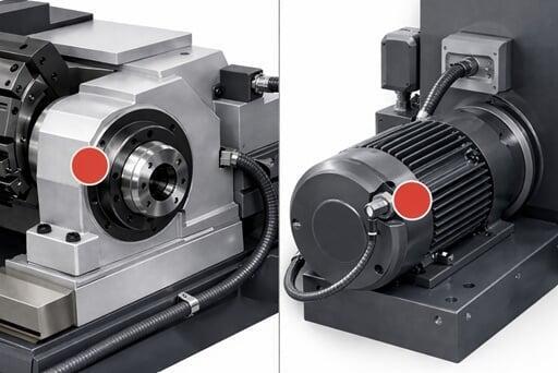
Spindle housing / headstock casting
The most common location for a CNC lathe spindle vibration sensor is the spindle housing or headstock casting:
- Closest practical location to the spindle bearings
- Sensitive to bearing defects, imbalance, and looseness
- Good indicator of overall spindle health and chatter-related issues
Spindle drive motor
Mounting a vibration sensor on the spindle drive motor:
- Captures motor bearing and rotor issues
- Helps distinguish between mechanical and electrical problems
- Lets you trend motor health independently of the spindle
Gearbox or belt drive (if present)
For lathes with gearboxes or belt drives:
- Sensors on the gearbox housing can pick up gear mesh, misalignment, or loose mounting
- Sensors near belt drives can reveal misaligned pulleys or loose belts that feed vibration into the spindle
Machine base or bed
In some applications, vibration sensors on the machine base or foundation can:
- Reveal structural issues or soft foot
- Detect vibration transmitted from nearby equipment that affects your lathe’s performance
Integrating CNC Lathe Vibration Sensors with Your Control System
An industrial vibration sensor for CNC lathe is only useful if you can see and act on the data.
PLC and CNC control integration
With a vibration transmitter tied into the spindle, you can:
- Send a 4–20 mA vibration signal into a PLC analog input
- Map that value into the CNC control via fieldbus or I/O
- Configure warnings, alarms, or interlocks based on vibration levels
This allows actions such as:
- Slowing the spindle when overall vibration exceeds a limit
- Triggering a warning message on the control
- Stopping the machine if vibration reaches a trip threshold
SCADA, historian, and condition monitoring systems
- Dynamic sensors with buffered outputs can feed:
- Portable data collectors for route-based analysis
- Online condition monitoring systems for continuous trending
- Plant historians so you can correlate vibration with tool changes, programs, or material changes
One strategy for all critical rotating assets
Using the same Metrix-style vibration hardware across pumps, fans, compressors, and CNC lathes simplifies:
- Spares
- Training
- Integration
- Alarm strategy
Your reliability program gets one consistent way to look at machine health.
How to Choose the Right Vibration Sensor for Your CNC Lathe
A few technical choices determine whether your CNC lathe vibration monitoring works well.
Frequency range and spindle speed
High-speed spindles demand sensors with:
- Wide frequency range to capture bearing fault frequencies and high-frequency content
- Proper sensitivity (commonly 100 mV/g) so you get usable signals without overloading
Mounting style and cable routing
For machine tools, it’s worth thinking through:
- Stud-mount vs adhesive mount bases
- Chip and coolant exposure along the cable route
- Strain relief to avoid cable-induced noise or premature failure
Environmental protection
Look for:
- Suitable temperature ratings near the spindle or motor
- IP ratings appropriate for coolant spray and chips
- Rugged connectors and cables compatible with the oils and coolants used
Output and wiring
Decide what each point needs to do:
- Dynamic output only where you’ll connect to a data collector or condition monitoring system
- Transmitter (4–20 mA) output where you simply need an overall vibration level in your PLC or CNC control
- Combination of both for critical points (spindle bearings) that need trending and detailed analysis
Application Support for CNC Lathe Vibration Monitoring
Specifying the right vibration sensor for CNC lathe spindles and motors is partly about the sensor, and partly about how it fits into your overall maintenance strategy.
Clipper Controls Inc. can help you:
- Identify critical points on each CNC lathe to monitor
- Select Metrix accelerometers and transmitters suited to your spindle speeds and environment
- Recommend mounting locations, bases, and cable routing
- Integrate signals into your existing PLC, CNC, SCADA, or condition monitoring system
If you’d like help specifying vibration sensors for one machine or an entire line of CNC lathes, you can call (844) 880-2469, or use the contact form on our website to send application details, spindle speeds, and photos of your machine
