Industrial Process Monitoring Camera for Process Control
Seeing the process is useful. Controlling the process is better.
When you need more than “video,” JM Canty process monitoring cameras can be configured as process control tools—turning real-time visuals into actionable signals for operators and PLC/DCS systems.
With the right combination of camera + lighting + mounting/window + VCM + CantyVision™ analytics, you can alarm, trend, and automate responses based on what’s happening in the process—without opening equipment or waiting for downstream quality checks.
👉 Ready to see if a process camera makes sense?
Similar Pages: Vision-Based Instrumentation | Process Analyzers | Food & BeverageProcess Control Applications | Refining & Chemical Process Control Applications | Life Science Process Control Applications
Why this is a process control solution (not just a camera)
A standard industrial camera helps you see the process. A process control monitoring camera system helps you control it by adding:
Analytics (CantyVision™): converts images into measurable variables (application dependent)
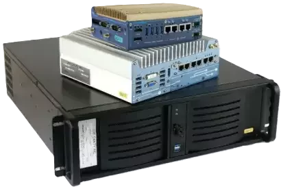
Edge processing (VCM): runs the analytics workflow and operator interface
Control-ready outputs: commonly configured for OPC UA / Modbus / 4–20 mA (configuration dependent)
Image → Measurement → Signal → Alarm/Action
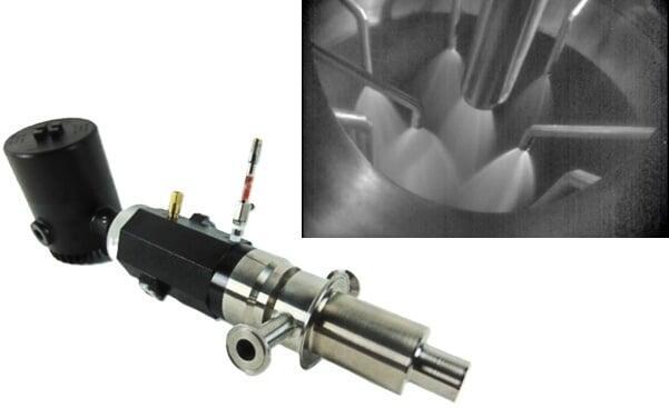
JM Canty Industrial Process Monitoring Camera System
- what variable you want (pattern deviation %, blockage detection, stability index, etc.)
- required interface (OPC UA / Modbus / 4–20 mA)
- alarm thresholds and required actions
- where the signal should land (PLC/DCS/SCADA/historian)
Camera + lighting (built for harsh environments)
- Rugged camera and enclosure options for industrial service
- Integrated or external lighting strategies (continuous or strobe, as needed)
- Optics selected for your working distance and target feature
Viewing interface (mounting, window, purge)
- Port/nozzle sizing and aiming support
- Window/sight-port strategy matched to temperature/chemistry
- Purge/air knife or cleaning approach to keep the view usable
VCM + CantyVision™ (where “monitoring” becomes “control”)
- VCM provides the compute layer for analytics and integration
- CantyVision™ generates variables/alarms for trending and control logic
- Outputs delivered to your PLC/DCS or SCADA environment (configuration dependent)
👉 Not sure which configuration you need?
Common applications
These are proven “camera + analytics” use cases where the output drives action:
Spray dryer monitoring
Use image-based monitoring to detect:
- spray pattern drift
- nozzle clogging or partial plugging
- pattern instability that can cause off-spec product or buildup risk
- changes in droplet size or distribution that indicate emerging problems
- alarm before quality issues cascade
- support operator intervention or automated corrective actions
- optimize CIP timing by spotting buildup trends earlier
- document spray performance as part of batch or lot records
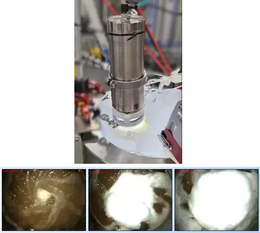
Froth control (biotech, pharma, and mining)
In biotech and pharma, excessive foam on fermenters and bioreactors can:
- blind exhaust filters
- trigger nuisance alarms
- drive overuse of antifoam and impact downstream steps
With a BioCam and VCM-based analytics, you can:
- monitor froth/foam height and coverage
- track changes in texture, bubble size, or stability over time
- generate variables and alarms that correlate with your “good” operating window
- reduce nuisance trips from foam and froth excursions
- optimize antifoam or reagent dosing instead of over-treating
- stabilize performance across shifts by giving operators and control systems the same, consistent froth/foam feedback
Vessels, mixers, and batch steps
- reduce “open and look” checks
- confirm phase behavior, agitation outcomes, or abnormal conditions
- create repeatable verification points during critical steps
- verify that solids are fully wetted or dissolved before advancing
- detect stratification, dead zones, or poor mixing early
- visually confirm CIP/SIP coverage and cleaning effectiveness
- document batch consistency with image-based records for QA/QC
👉 Have a tricky application?
Integration notes for controls engineers
- Interfaces (configuration dependent): OPC UA, Modbus, 4–20 mA
- Alarm logic: warning vs trip/interlock setpoints
- Trending: historian-ready variables for batch records and optimization
- Network access: remote operator/engineering access (as required by IT/OT policies)
- Architecture: camera(s) + lighting + window/purge + VCM analytics + PLC/DCS outputs
What to specify (RFQ checklist)
Process conditions
- normal/upset temperature
- pressure/vacuum
- dust/abrasives or sticky vapors
- corrosive chemistry exposure
- washdown requirements (sanitary/CIP/SIP)
Mechanical + optical
- port/nozzle size and location
- desired field of view (what you need to see/measure)
- working distance and target feature size
- window/sight port requirements
- purge/cleaning approach (to avoid fouled optics)
Controls + outputs
- what variable you want (pattern deviation %, blockage detection, stability index, etc.)
- required interface (OPC UA / Modbus / 4–20 mA)
- alarm thresholds and required actions
- where the signal should land (PLC/DCS/SCADA/historian)
Why buy through Clipper Controls
- the camera survives, but can’t see what matters (bad angle, wrong optics, glare, fouling)
- you get video, but no usable signal for control
- there’s no plan for window/purge/cleaning, so the image degrades over time

👉 Need help specifying a process monitoring camera in CA, NV, or HI?
