AC Current Transducers
For Accurate Industrial Power Monitoring and Control
What Is an AC Current Transducer and Why It Matters
From AC current to DC signal – the basics
- 4–20 mA DC
- 0–10 V DC (sometimes 0–5 V)
- 0–100 A AC → 4–20 mA DC
- 0–50 A AC → 0–10 V DC
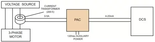
How AC current transducers fit into automation and control systems
- Mounted in motor control centers (MCCs), electrical panels, or switchgear
- Connected to the load via a current transformer (CT) or directly (for low currents)
- Providing a 4–20 mA or 0–10 V signal into analog inputs on:
- PLCs
- DCS or RTUs
- SCADA-connected I/O
- Energy management or power monitoring systems
- Motor loading and imbalance
- Feeder currents
- Panel loading and capacity
- Energy consumption by area or process
👉 If you need to bring AC current signals cleanly into your PLC, DCS, or SCADA system, Clipper Controls can help you specify AC current transducers matched to your I/O and application requirements. Contact us today!
True RMS AC Current Transducers in Demanding Industrial Environments
Why true RMS measurement is critical in modern power systems
- Variable frequency drives (VFDs)
- Soft starters
- UPS systems
- Switching power supplies
- LED lighting and electronic ballasts
- Accurate current readings even with high harmonic content
- Correct loading values for equipment and feeders
- More reliable alarms, trips, and trending
Avoiding under- or over-reporting current with average-responding devices
- Under-reporting current when waveforms are heavily distorted, hiding thermal stress on cables, transformers, and motors.
- Over-reporting current in some situations, creating nuisance alarms or leading to unnecessary equipment upsizing.
- Better correlation between current trends and actual equipment behavior
- Fewer “mystery” overloads that don’t match the readings
- More confidence in thresholds set for protection, alarming, and analytics
Applications that benefit most from true RMS AC current measurement
- Motor control centers (MCCs) feeding VFD-driven motors
- UPS systems and data centers with high electronic loads
- HVAC systems with variable-speed fans and pumps
- Process plants and refineries using VFDs on large pumps, compressors, and blowers
- Power generation and cogeneration facilities where power quality and loading are tightly managed
👉 To ensure accurate measurement on distorted waveforms and VFD-fed loads, work with Clipper Controls to select true RMS AC current transducers tailored to your MCCs, panels, and process loads.
Signal Isolation and Conditioning for Reliable Control System Inputs
Why galvanic isolation in current transducers protects your control system
- Ground loops and noise coupling
- Damage to analog input cards from faults or transients
- Unstable readings that make trend data unreliable
- The AC input (high-voltage side) and
- The DC output (control system side)
Filtering, scaling, and linearization for clean analog signals
- Filtering to reject noise and reduce high-frequency interference
- Scaling and span settings so output ranges match your measurement range (e.g., 0–50 A → 4–20 mA)
- Linearization to maintain accuracy across the specified measurement range
- Configuration options for different frequency ranges and response times
Choosing the Right AC Current Transducer for Industrial Control
Define your primary measurement objective
- Protection – monitoring current levels for overload or fault detection
- Real-time monitoring – providing operators with live loading information
- Energy management – measuring current as part of kW/kWh and demand monitoring
- Load sharing and balancing – matching loads across phases or feeders
- Predictive maintenance – trending current over time to identify mechanical or electrical degradation
Key selection criteria
- Input current range – e.g., 0–5 A (via CT), 0–50 A, 0–100 A, etc.
- Frequency range – typically 50/60 Hz, sometimes wider for specific applications
- Output signal – 4–20 mA, 0–10 V, or other standardized DC outputs
- Accuracy and linearity – especially important for energy management and billing-related data
- Isolation voltage rating – to withstand expected fault levels and transient conditions
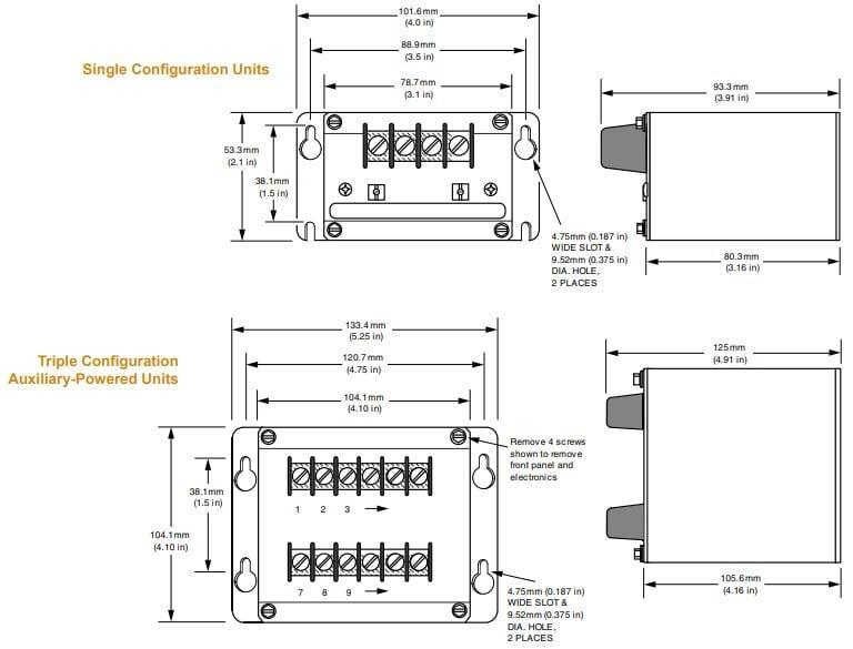
- Mounting and form factor – DIN-rail vs. panel-mount, space constraints in your electrical panels
- Environmental ratings – temperature, humidity, vibration, and enclosure type
- Certifications and approvals – as required by your industry or jurisdiction
Matching transducer performance to your PLC/SCADA I/O
- I/O type and range – Ensure your PLC or RTU analog inputs are compatible with 4–20 mA or 0–10 V.
- Loop-powered vs. externally powered – Decide whether the transducer will be powered by the loop or a separate supply.
- Load resistance – Confirm that the loop resistance is within the transducer’s specifications.
- Wiring practices – Use twisted-pair, shielded cable as appropriate; follow grounding and routing best practices.
👉 Not sure which AC current transducer best fits your MCC, panel, or SCADA I/O? Contact Clipper Controls to review your application and get a recommended solution.
Application Examples – Where AC Current Transducers Deliver Value
Current monitoring in motor control centers and electrical panels
- Individual motor loads and phase imbalance
- Feeder and branch circuit currents
- Total panel loading versus capacity
This visibility supports:
- Overload and trip analysis
- Load balancing and capacity planning
- Motor health monitoring (e.g., increasing current over time)
Energy management and load analysis across the facility
- Submetering feeders and large loads
- Identifying energy-intensive equipment or processes
- Supporting demand response and peak shaving strategies
- Reduce energy costs
- Optimize equipment scheduling
- Support sustainability reporting
Power generation, utility substations, and critical distribution panels
- Generator and transformer load monitoring
- Feeder and bus current measurement
- Protection system inputs and SCADA status points
Process plants, refineries, and heavy industrial loads
- Large pumps and compressors
- Induced draft and forced draft fans
- Mixers, agitators, and conveyors
- Electric heaters and furnaces
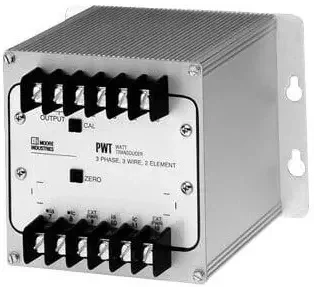
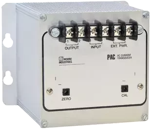
Moore Industries PAC Series True RMS AC Current Transducers
Overview of the Moore Industries PAC series
- True RMS measurement for accurate readings on distorted waveforms
- Wide AC current input ranges
- Standard 4–20 mA or 0–10 V DC outputs
- Compact form factors suitable for dense panel layouts
Key features for demanding industrial environments
- High isolation between input, output, and power to protect sensitive control equipment
- Wide input range options to cover various feeder and load currents
- Configurable outputs for flexibility in integration (4–20 mA or voltage outputs)
- Robust immunity to electrical noise, ideal for MCCs, substations, and manufacturing panels
- Rugged construction to withstand industrial vibration, temperature changes, and long service life demands
Integrating Moore AC transducers into PLC and SCADA architectures
- Scalable 4–20 mA outputs wired directly into analog input modules
- Clear labeling and terminals that simplify installation and maintenance
- Flexible configuration to match site standards and I/O expectations
👉 To learn how Moore Industries PAC series AC current transducers can be applied in your MCCs, electrical panels, and utility systems, contact Clipper Controls for application support and product selection.
Installation, Configuration, and Maintenance Best Practices
Proper installation for accurate AC current measurement
- Use appropriately rated current transformers (CTs) or direct-connect inputs within specified ranges.
- Observe proper CT polarity and orientation to avoid negative or inverted readings.
- Route transducer wiring away from high-noise conductors where possible.
- Secure mounting in panels or MCCs to minimize vibration and mechanical stress.
Configuration tips for 4–20 mA and 0–10 V outputs
- Selecting the correct input range (e.g., 0–50 A vs. 0–100 A)
- Scaling the 4–20 mA or 0–10 V output to match your PLC or SCADA configuration
- Verifying that analog input modules are configured for the correct signal type (current vs. voltage)
- Using built-in test points or diagnostic LEDs as available
Verifying performance and troubleshooting common issues
- Common issues and quick checks include:
- No signal – check power, wiring polarity, blown fuses, and CT secondary connections.
- Erratic readings – inspect grounding, cable shielding, and separation from high-noise conductors.
- Out-of-range or saturated signals – verify that input current is within range and that CT ratios are correctly matched.
- Inconsistent trends – confirm that scaling values in the PLC/SCADA match the transducer’s configured range.
Using monitoring trends for predictive maintenance
- Gradual increases in motor current may indicate bearing wear, misalignment, or mechanical binding.
- Load changes over time can highlight process drift, clogging, or fouling in pumps and fans.
- Inconsistent current behavior under constant conditions may point to electrical issues like insulation breakdown or poor connections.
How AC Current Transducers Improve Power Monitoring and Reliability
Enhancing power monitoring accuracy across your facility
- Improve the quality and reliability of data feeding your power and energy dashboards
- Help correlate electrical behavior with process and equipment performance
- Enable better decision-making on asset loading, capacity, and upgrades
Supporting energy efficiency and sustainability initiatives
- Identifying underutilized or oversized equipment
- Highlighting processes that drive peak demand charges
- Providing before-and-after data for efficiency projects and retrofits
Reducing unplanned downtime with data-driven maintenance
- Abnormal current behavior is often an early warning of mechanical or electrical problems.
- Plant-wide current data across MCCs, panels, and processes supports more targeted inspections and repairs.
- Data-driven maintenance decisions help reduce unexpected failures and improve overall asset utilization.
👉 If you’re working to improve power monitoring accuracy and reliability, consider where AC current transducers can add visibility to your electrical systems. Clipper Controls can help design and support a fit-for-purpose current monitoring strategy.
Partner with Clipper Controls for AC Current Measurement Solutions
- Improve power monitoring accuracy
- Support energy management and sustainability goals
- Enable predictive maintenance strategies
- Protect PLC, DCS, and SCADA systems from electrical disturbances
- Enhance the reliability and safety of your electrical infrastructure
- Providing application support for industrial AC current measurement
- Offering Moore Industries AC current transducers, including the PAC series
- Recommending appropriate signal conditioning, isolation, and interface solutions for MCCs, electrical panels, substations, and process units
- Helping integrate these devices into PLC, DCS, SCADA, and energy management systems

👉 Need help specifying a current transducer in CA, NV, or HI?
